Ankit works in the Mechanical Maintenance Division of Hot Strip Mill, Jindal Stainless in India. He has keen interest in HVAC , Hot Rolling Machinery & Equipment, and Industrial Hydraulics.
Creep Deformation
01.03.2022
Table of Contents
Background
The meaning of creep as per the English dictionary is as follows: creep is essentially an act of moving slowly and carefully in order to avoid being heard or noticed. Well, this is what people studying English literature would think of creep but for us, engineers or scientists, creep very interestingly indicates the same. So in a very generic fashion, if we have to define creep, Creep refers to plastic deformation that generally happens so slowly that it remains imperceptible by and large, but could suddenly surprise you with the enormity of its damage unless it is closely studied, monitored, and accounted for. So you can clearly see the kind of analogy that one can draw with the English dictionary definition of creep. So creep is going to happen slowly, move slowly and so slowly so there is a correlation there and because it happens slowly it is not dynamic enough such that you will not know that deformation is occurring by creep but creep plays an important role because the damage that happens in the wake of creep could be enormous and hence it is necessary to study it closely and account for it when you design and maintain a product.
Introduction
Creep may be defined as a time-dependent deformation at elevated temperature and constant stress. It follows, then, that a failure from such a condition is referred to as a creep failure or, occasionally, a stress rupture. The temperature at which creep begins depends on the alloy composition.
At elevated temperatures and stresses that are much less than the high-temperature yield stress, metals undergo permanent plastic deformation called creep. Figure 1 shows a schematic creep curve for a constant load; a plot of the change in length versus time. The weight or load on the specimen is held constant for the duration of the test. There are four portions of the curve that are of interest:
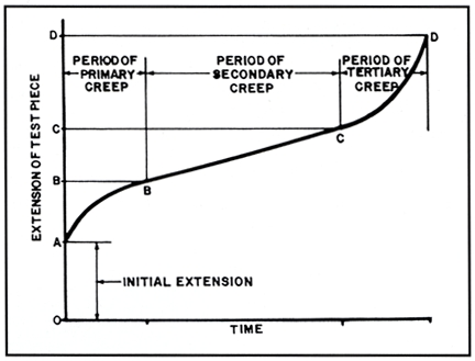
Figure 1. Schematic creep curve. Courtesy Babcock & Wilcox.

An initial steep rate that is at least partly of elastic origin, from point “0” to point “A” in Figure 1.
This is followed by a region in which the elongation or deformation rate decreases with time, the so-called transient or primary creep, from region “A” to “B” of Figure 1. The portion from point “0” to point “B” occurs fairly quickly. The next portion of the creep curve is the area of engineering interest, where the creep rate is almost constant. The portion from “B” to “C” is nearly linear and predictable. Depending on the load or stress, the time can be very long; two years in a test and several decades in service.
The fourth portion of the creep curve, beyond the constant-creep-rate or linear region, shows a rapidly increasing creep rate which culminates in failure. Even under constant-load test conditions, the effective stress may actually increase due to the damage that forms within the microstructure.
Without going into a detailed discussion of the atom movements involved in creep deformation, suffice it to say that creep deformation occurs by grain-boundary sliding. That is, adjacent grains or crystals move as a unit relative to each other. Thus, one of the microstructural features of a creep failure is little or no obvious deformation to individual grains along the fracture edge.
The first two stages will not leave any microstructural evidence of creep damage. Somewhere along the linear portion of Figure 1, the first microstructural evidence of damage appears as individual voids or pores. The location of these first voids or holes varies, often noted at the junction of three or more grains, occasionally at nonmetallic inclusions. These individual voids grow and link to form cracks several grains long, and finally, failure occurs. The ultimate rupture is by a tensile overload when the effective wall thickness is too thin to contain the steam pressure.
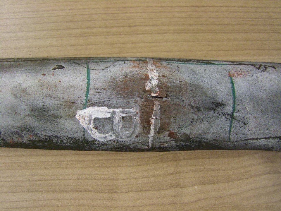

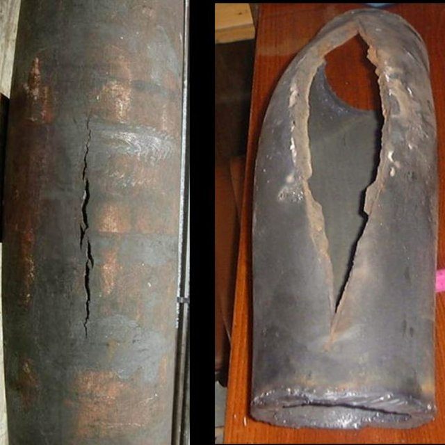
Figure 2: Failure of a boiler tube due to creep
Deep-Diving into Creep
Mechanisms of creep
The mechanism of creep depends on temperature and stress. The various methods are:
- Thermally activated glide – e.g., via cross-slip
- Climb assisted glide – here the climb is an enabling mechanism, allowing dislocations to get around obstacles
- Climb – here the strain is accomplished by a climb
- Grain boundary diffusion
- Bulk diffusion
The most common mechanism is climb-assisted glide.
General creep equation
![]()
where ε is the creep strain, C is a constant dependent on the material and the particular creep mechanism, m and b are exponents dependent on the creep mechanism, Q is the activation energy of the creep mechanism, σ is the applied stress, d is the grain size of the material, k is Boltzmann’s constant, and T is the absolute temperature.
Dislocation creep
At high stresses (relative to the shear modulus), creep is controlled by the movement of dislocations. When stress is applied to a material, plastic deformation occurs due to the movement of dislocations in the slip plane. Materials contain a variety of defects, for example, solute atoms, that act as obstacles to dislocation motion. Creep arises from this because of the phenomenon of dislocation climb. At high temperatures vacancies in the crystal can diffuse to the location of dislocation and cause the dislocation to move to an adjacent slip plane. By climbing to adjacent slip planes dislocations can get around obstacles to their motion, allowing further deformation to occur. Because it takes time for vacancies to diffuse to the location of a dislocation this results in time-dependent strain, or creep.
For dislocation creep Q = Qself diffusion, m = 4-6, and b=0. Therefore dislocation creep has a strong dependence on the applied stress and no grain size dependence.
Some alloys exhibit a very large stress exponent (n > 10), and this has typically been explained by introducing a “threshold stress,” σth, below which creep can’t be measured. The modified power-law equation then becomes:
![]()
where A, Q, and n can all be explained by conventional mechanisms (so ![]()
Nabarro-Herring Creep
Nabarro-Herring creep is a form of diffusion-controlled creep. In N-H creep atoms diffuse through the lattice causing grains to elongate along the stress axis. For Nabarro-Herring creep k is related to the diffusion coefficient of atoms through the lattice, Q = Qself diffusion, m=1, and b=2. Therefore N-H creep has a weak stress dependence and a moderate grain size dependence, with the creep rate decreasing as grain size is increased.
Nabarro-Herring creep is found to be strongly temperature-dependent. For lattice diffusion of atoms to occur in a material, neighboring lattice sites or interstitial sites in the crystal structure must be free. A given atom must also overcome the energy barrier to move from its current site (it lies in an energetically favorable potential well) to the nearby vacant site (another potential well). The general form of the diffusion equation is D = DoExp(Ea / KT) where Do has a dependence on both the attempted jump frequency and the number of nearest-neighbor sites and the probability of the sites being vacant.
Thus there is a double dependence upon temperature. At higher temperatures the diffusivity increases due to the direct temperature dependence of the equation, the increase in vacancies through Schottky defect formation, and an increase in the average energy of atoms in the material. Nabarro-Herring creep dominates at very high temperatures relative to a material’s melting temperature.
Coble Creep
Coble creep is a second form of diffusion-controlled creep. In Coble creep the atoms diffuse along grain boundaries to elongate the grains along the stress axis. This causes Coble creep to have a stronger grain size dependence than N-H creep. For Coble creep k is related to the diffusion coefficient of atoms along the grain boundary, Q = Qgrain boundary diffusion, m=1, and b=3. Because Qgrain boundary diffusion < Qself diffusion, Coble creep occurs at lower temperatures than N-H creep.
Coble creep is still temperature-dependent, as the temperature increases so do the grain boundary diffusion. However, since the number of nearest neighbors is effectively limited along with the interface of the grains, and thermal generation of vacancies along the boundaries is less prevalent, the temperature dependence is not as strong as in Nabarro-Herring creep. It also exhibits the same linear dependence on stress as N-H creep.
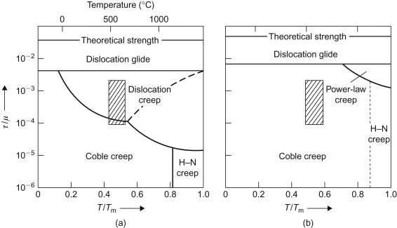
Sometimes the dislocation creep field is further divided into two fields: low- and high-temperature dislocation creep fields. At further low stresses, volume diffusion creep (Nabarro–Herring creep) and grain boundary diffusion creep (Coble creep) dominate. The boundaries between adjacent fields in the creep region indicate the conditions under which two mechanisms contribute equally to the overall creep rate. Using an appropriate constitutive equation for creep rates as functions of stress and temperature, we can calculate the creep rates and can draw the boundaries. This also allows us to plot the contours of constant creep rate onto the map, as shown schematically in Fig. 2.
Figure 2. Schematic deformation mechanism map with contours of constant creep rate.
Creep of Polymers
Creep can occur in polymers and metals which are considered viscoelastic materials. When a polymeric material is subjected to an abrupt force, the response can be modeled using the Kelvin-Voigt Model. In this model, the material is represented by a Hookean spring and a Newtonian dashpot in parallel. The creep strain is given by:
![]()
Where:
σ = applied stress
C0 = instantaneous creep compliance
C = creep compliance coefficient
τ = retardation time
f(τ) = distribution of retardation times
When subjected to step-constant stress, viscoelastic materials experience a time-dependent increase in strain. This phenomenon is known as viscoelastic creep.
At a time t0, a viscoelastic material is loaded with constant stress that is maintained for a sufficiently long time period. The material responds to the stress with a strain that increases until the material ultimately fails. When the stress is maintained for a shorter time period, the material undergoes an initial strain until a time t1, after which the strain immediately decreases (discontinuity) then gradually decreases at times t > t1 to a residual strain.
Viscoelastic creep data can be presented in one of two ways. Total strain can be plotted as a function of time for a given temperature or temperatures. Below a critical value of applied stress, a material may exhibit linear viscoelasticity. Above this critical stress, the creep rate grows disproportionately faster. The second way of graphically presenting viscoelastic creep in a material is by plotting the creep modulus (constant applied stress divided by total strain at a particular time) as a function of time. Below its critical stress, the viscoelastic creep modulus is independent of stress applied. A family of curves describing strain versus time response to various applied stresses may be represented by a single viscoelastic creep modulus versus time curve if the applied stresses are below the material’s critical stress value.
Additionally, the molecular weight of the polymer of interest is known to affect its creep behavior. The effect of increasing molecular weight tends to promote secondary bonding between polymer chains and thus make the polymer more creep resistant. Similarly, aromatic polymers are even more creep resistant due to the added stiffness from the rings. Both molecular weight and aromatic rings add to polymers’ thermal stability, increasing the creep resistance of a polymer. (Meyers and Chawla, 1999, 573)
Both polymers and metals can creep. Polymers experience significant creep at all temperatures above ~-200°C, however, there are three main differences between polymeric and metallic creep.
Metallic creep:-
- is not linearly viscoelastic
- in not recoverable
- only significant at high temperatures
Facts and Examples
- The Collapse of the World Trade Center was due in part to creep from increased temperature operation.
- The creep rate of hot pressure-loaded components in a nuclear reactor at power can be a significant design constraint since the creep rate is enhanced by the flux of energetic particles.
- Creep was blamed for the Big Dig tunnel ceiling collapse in Boston, Massachusetts that occurred in July 2006.
Since creep deformation occurs by grain-boundary sliding, the more grain boundary area, the easier creep deformation will be. Creep deformation and creep strength are a grain-size sensitive property. Thus a larger grain size improves creep strength. For austenitic stainless steels, SA213 TP321H for example, the code requires a grain size of #7 or coarser, to assure adequate creep strength. The elevated temperatures where creep occurs lead to other microstructural changes.
Creep damage and microstructural degradation occur simultaneously. For carbon steels and carbon-1/2 molybdenum steels, iron carbide will decompose into graphite. For the low-alloy steels of T-11 and T-22, the carbide phase spheroidized. Thus, creep failures will include the degraded microstructures of graphite or spheroidized carbides along with the grain-boundary voids and cracks characteristic of these high-temperature, long-time failures.
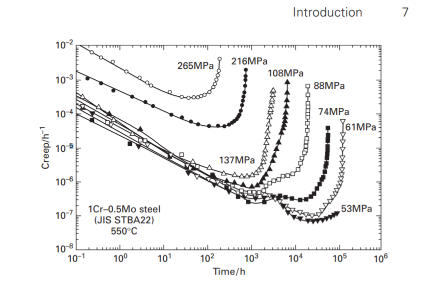
Figure 3:- Creep rate versus time curves of 1Cr–0.5Mo steel at 550°C (823K).
Creep deformation is important not only in systems where high temperatures are endured such as nuclear power plants, jet engines, and heat exchangers but also in the design of many everyday objects. For example, metal paper clips are stronger than plastic ones because plastics creep at room temperatures. Aging glass windows are often erroneously used as an example of this phenomenon: creep would only occur at temperatures above the glass transition temperature around 900°F/500°C.
At stresses lower than the ideal strength, fracture takes place in a ductile, transgranular way, designated ductile fracture, and often designated ductile transgranular fracture. In the creep regime, two fields of transgranular creep fracture and intergranular creep fracture appear at high and low stresses, respectively. At high temperatures and relatively high strain rates, dynamic recrystallization can allow materials to deform extensively so that deformation becomes localized in a neck and failure eventually occurs by the specimen necking until the cross-sectional area has gone to zero, usually called the field of rupture. Because grain boundaries become highly mobile under conditions of dynamic recrystallization, the development of creep voids and cavities is suppressed. Figure 4 shows schematically the three fracture mechanisms in the creep regime: intergranular creep fracture, transgranular creep fracture, and rupture.
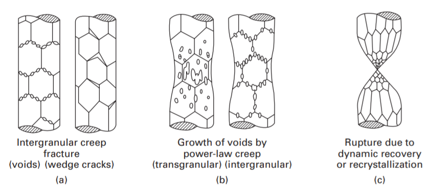
Figure 4:- Schematic drawing of three fracture mechanisms in a high temperature creep regime.
An example of an application involving creep deformation is the design of tungsten lightbulb filaments. Sagging of the filament coil between its supports increases with time due to creep deformation caused by the weight of the filament itself. If too much deformation occurs, the adjacent turns of the coil touch one another, causing an electrical short and local overheating, which quickly leads to failure of the filament. The coil geometry and supports are therefore designed to limit the stresses caused by the weight of the filament, and a special tungsten alloy with small amounts of oxygen trapped in the crystallite grain boundaries is used to slow the rate of coble creep.
In steam turbine power plants, steam pipes carry superheated vapor under high temperatures (1050°F/565.5°C) and high pressure often at 3500 psi or greater. In a jet engine, temperatures may reach 1000°C, which may initiate creep deformation in a weak zone. For these reasons, it is crucial for public and operational safety to understand the creep deformation behavior of engineering materials.
References
- https://www.nationalboard.org/
- Kowalewski Z.L., Ustrzycka A. (2020) Creep Deformation. In: Altenbach H., Öchsner A. (eds) Encyclopedia of Continuum Mechanics. Springer, Berlin, Heidelberg. https://doi.org/10.1007/978-3-662-55771-6_157
- https://www.chemeurope.com/en/encyclopedia/Creep_%28deformation%29.html
- TABOR, D., WALKER, J. Creep and Friction of Ice. Nature 228, 137–139 (1970). https://doi.org/10.1038/228137a0
Be the first to comment