Plastic Deformation at Microscale
What is plastic deformation?
Plastic deformation, in general, can be defined as a permanent deformation, a non-reversible change in the geometry of a body under applied stresses (forces). For example, if hit sufficiently hard by a piece of rock or hail, a car body made of metal gets a dent (irreversible deformation). On the other hand, rubber is an example of a material which exhibits highly elastic behaviour: you can stretch it to a high degree, but once the force is released rubber returns to its original shape. Plastic deformation occurs at a certain critical stress (force) beyond which the deformation is irreversible. This transition is known as yield. Plastic deformation may occur in most engineering materials including metals, soils, rocks, concrete, foams. However, in different materials, the mechanisms responsible for plastic deformation can be different: dislocation motion, vacancy motion, twinning, phase transformation, or viscous flow of amorphous materials.
Plastic deformation in metals
In metals, room temperature plastic deformation occurs as a consequence of the collective motion of dislocations gliding on specific slip planes. In continuum plasticity formulations, the effect of individual dislocations is ignored and hence, such descriptions are not suitable for applications such as the development of devices with characteristic length scales in the micrometre range (e.g. MEMS).
In Fig. 1, the various relevant scales (macro- to nano-scale) determining the response of metals during plastic deformation are demonstrated. As one can observe at macro-scale the plastic zone is governed by continuum plastic flow (Fig. 1(b)). Inside this plastic region, the material is polycrystalline with the plastic deformation being different in different grains (Fig. 1(c)). By magnifying this region, it can be recognized that at the micro-scale plastic deformation occurs as a consequence of the collective motion of dislocations gliding on specific slip planes (Fig. 1(d)). It is the mobility of these dislocations that gives rise to plastic flow at stress levels relatively low compared to the theoretical strength (see [1]). Finally, at the nano-scale, the atomic arrangement of the material is revealed (Fig. 1(e)). At this scale, dislocations are shown to be irregularities within the crystal structure.
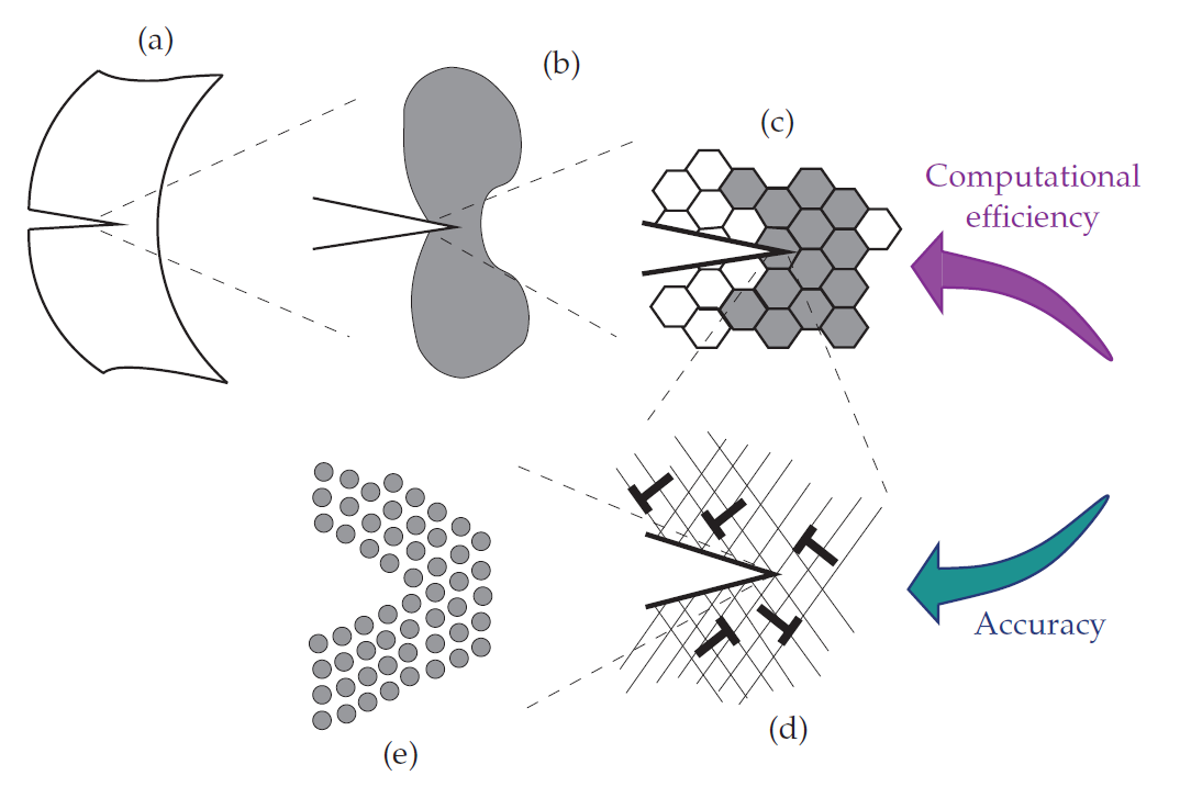
Figure 1 illustrates that as one approaches smaller length scales the amount of the physics captured in these models increases, yet this is achieved by the expense of heavier and higher calculation times. The difference between the plasticity models at various scales is based on how they describe dislocation motions and interactions:
- Continuum and (ploy)crystal models (macro- and meso-scales): These models consist of phenomenological continuum and crystal plasticity theories which consider the average motion of groups or densities of dislocations. These theories are employed at the size scale of Figs. 1(a)-1(c), i.e. when the length scale of the specimen exceeds the size of the individual grains or when the number of dislocations in the material is large. For describing plasticity at this scale accounting for dislocation densities will suffice and there is no need to consider individual dislocations. Examples of these models can be found in Groma (1997) [3] and Fleck et al. (1994) [4].
- Discrete dislocation models (micro-scale): These methods describe plastic flow in terms of the dynamics of large numbers of interacting discrete dislocations while taking into account individual behaviour of every dislocation inside crystals (Fig. 1(d)). As a result, these frameworks may give an accurate description of the material behaviour when specimen size gets within the micrometre range. Hence, these models are mainly employed to enhance the understanding of defect interactions and also to provide better assumptions for the parameters used in meso-scale plasticity models. Examples of these methods include Zbib et al. (2002) [5], van der Giessen and Needleman (1995) [6], Irani et al. [7], and Lepinoux and Kubin (1987) [8].
- Atomistic models (nano-scale): The discrete dislocation based methods require governing laws for individual dislocations and their short-range interactions with each other. The constitutive laws at the nano-scale are difficult to obtain experimentally and therefore, they are usually investigated by atomistic models at the size scale of Fig. 1.1(e). For examples of these methods see Bernstein et al. (2009) [9], and Curtin and Miller (2003) [10].
Here, as an example of micro-scale plasticity techniques, the discrete dislocation plasticity (DDP) of van der Giessen and Needleman (1995) [6] is presented. In this framework, plastic deformation and flow are described by the nucleation and glide of discrete edge dislocations. Here, a brief and general summary of the DDP formulation in a small strain setting is provided:
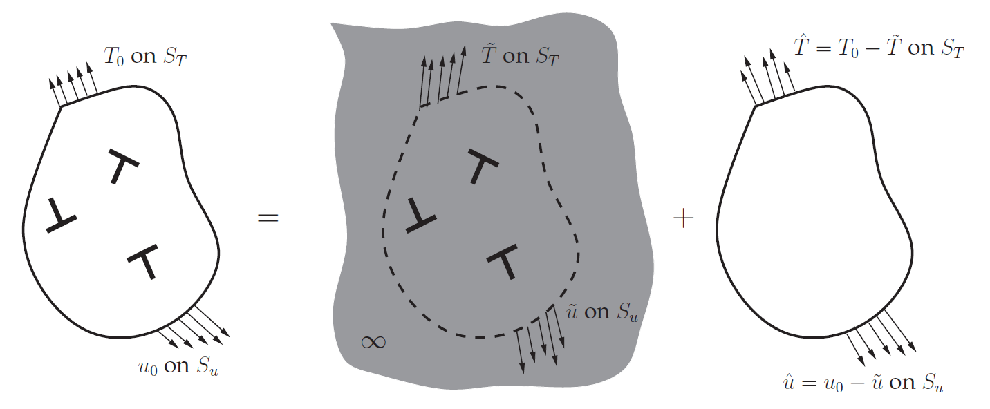
Consider a two-dimensional body under plane strain conditions such that at time t, the body contains N edge dislocations, with the dislocations being represented as line singularities in an elastic medium. In this method, to obtain the solution, the problem is decomposed in two additive parts and the field quantities are computed using superposition (see Fig. 2). First, the singular (˜) fields associated with the N dislocations are calculated analytically. In this method, typically the analytically calculated dislocations fields in an infinite medium are used to represent the (˜) fields. Thus, these fields do not give the correct stress and displacement fields at the boundaries. This issue is solved by solving for a complementary problem, where both the boundary conditions and the dislocation fields are applied (see Fig. 2). Thus, the complementary problem is an elasticity boundary value problem with its boundary conditions changing as the dislocation structure evolves. One may solve the complementary problem by employing conventional finite element methods.
At the beginning of a calculation the crystal is stress- and dislocation-free. New dislocation pairs are generated by simulating Frank-Read sources. In two dimensions, this is mimicked by discrete point sources randomly distributed on the slip planes. These sources generate a dislocation dipole with their Burgers vectors aligned with the slip plane direction. This occurs when the magnitude of the Peach-Koehler force on a source exceeds a critical value for a certain time. Annihilation of two opposite signed dislocations on a slip plane occurs when they are within a material-dependent critical annihilation distance. The magnitude of the glide velocity along the slip direction of a dislocation is taken to be linearly related to the Peach-Koehler force. Obstacles to dislocation motion are modelled as points associated with a slip plane. The dislocations gliding on the slip plane of an obstacle, get pinned as they try to pass through this obstacle. Moreover, obstacles release the pinned dislocations when the Peach-Koehler force on the obstacle exceeds a critical value.
(a)
(b)
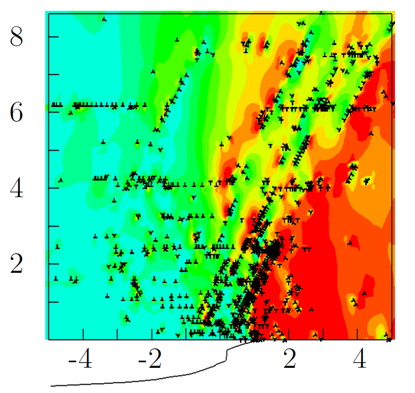
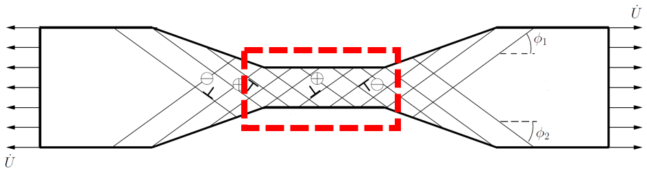
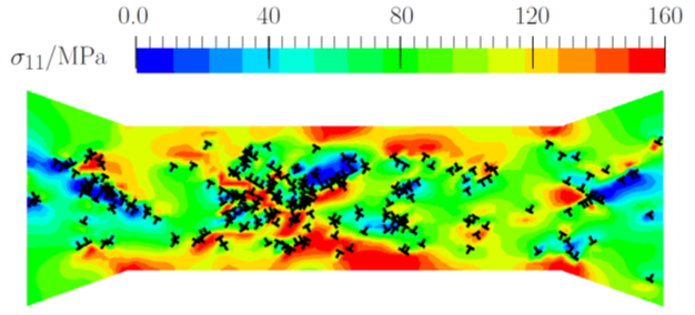
Figure 3: (a) Sketch of the uniaxial tension of a dog-bone specimen at the micro-scale with the window over which the dislocation distributions are shown in (b). The crystal is shown in the double slip configuration. (b) A snapshot of DDP predictions of the dislocation and tensile stress σ11 distributions [11].
Figure 3(a) demonstrates a metallic dog-bone specimen under tensile loading at the micro-scale. As it is shown, at this length-scale, we must treat the specimen as a crystalline material with discrete slip planes. Figure 3(b) illustrates that by using discrete dislocation plasticity we have been able to model the individual behaviour of every dislocation inside the crystal. As a result, we could account for both the stress enhancement due to organized dislocation structures and the stress relaxation arising from dislocation glide. For more information on this topic, the interested reader is referred to [12].
References
- [1] https://en.wikipedia.org/wiki/Dislocation
- [2] van der Giessen, E. and Needleman, A. (2003). Dislocation plasticity effects on interfacial fracture. Interface Science, 11(3):291–301.
- [3] Groma, I. (1997). Link between the microscopic and mesoscopic length-scale description of the collective behavior of dislocations. Physical Review B, 56(10):5807–5813.
- [4] Fleck, N. A., Muller, G. M., Ashby, M. F., and Hutchinson, J. W. (1994). Strain gradient plasticity: theory and experiment. Acta Metallurgica et Materialia, 42(2):475–487.
- [5] Zbib, H. M., de la Rubia, T. D., and Bulatov, V. (2002). A multiscale model of plasticity based on discrete dislocation dynamics. Journal of Engineering Materials and Technology, 124:78–87.
- [6] van der Giessen, E. and Needleman, A. (1995). Discrete dislocation plasticity: a simple planar model. Modelling and Simulation in Materials Science and Engineering, 3:689–735.
- [7] N. Irani , J.J.C. Remmers and V.S. Deshpande, 2015. Finite strain discrete dislocation plasticity in a total Lagrangian setting. Journal of the Mechanics and Physics of Solids, 83 (2015), 160–178.
- [8] Lepinoux, J. and Kubin, L. P. (1987). The dynamic organization of dislocation structures: a simulation. Scripta metallurgica, 21(6):833–838.
- [9] Bernstein, N., Kermode, J. R., and Csanyi, G. (2009). Hybrid atomistic simulation methods for materials systems. Reports on Progress in Physics, 72(2):026501
- [10] Curtin, W. A. and Miller, R. E. (2003). Atomistic/continuum coupling in computational materials science. Modelling and simulation in materials science and engineering, 11(3):R33–R68.
- [11] Irani, N., Remmers, J. J. C., Deshpande, V. S., (2017). Finite versus small strain discrete dislocation analysis of cantilever bending of single crystals. Acta Mechanica Sinica, 33.4: 763-777.
- [12] Irani, N., 2016. Finite strain discrete dislocation plasticity: applications and new developments. Eindhoven University of Technology, The Netherlands.
- [13] Irani, N., Remmers, J. J. C., Deshpande, V. S., (2017). A discrete dislocation analysis of hydrogen-assisted mode-I fracture. Mechanics of Materials 105: 67-79.
Be the first to comment