

Industrial Engineer with focus on Tribology and Sealing Technology. Team player with an open-minded mentality author of several scientific publications and an industrial patent. Interested in Lean Management, Innovation, Circular Economy, Additive Manufacturing and Connected Objects Technology.
Coefficient of Friction derivation in Reciprocating Contacts
Table of Contents
Reciprocating contacts are common in many engineering applications, e.g., hydraulic/pneumatic cylinders, crank-slider mechanisms (piston rings-cylinder), fretting vibrations, cyclic stresses, etc. The coefficient of friction in a reciprocating contact is usually detrimental when designing the component and often determines the mechanism service time. A higher coefficient of friction predicts a shorter lifespan in fretting fatigue for example [1]. Oscillating tribometers (or reciprocating tribometers) replicate the nature of these contacts so the tribological characteristics of the real component contact can be simulated in the lab (model scale).
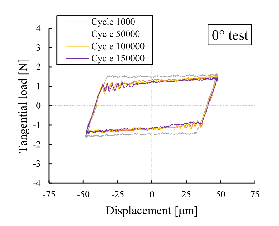
The frictional characteristics of a reciprocating (or oscillating) contacts are usually presented using the tangential force hysteresis loop (also referred to as “fretting loop”), i.e., the tangential force Q (y-axis) over its position Δ (x-axis) along a full cycle: forward and back strokes.
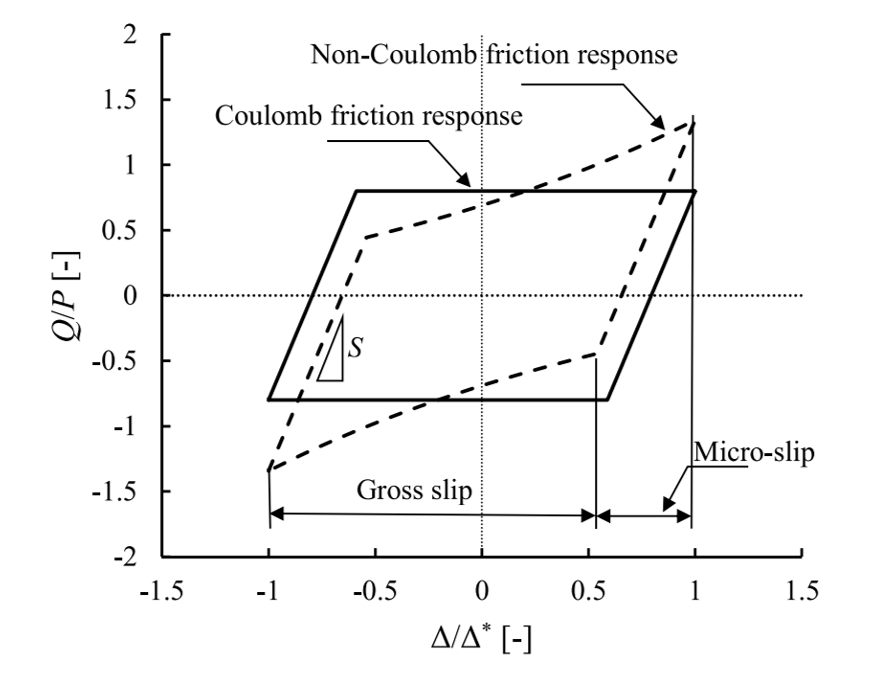
Figure 1. Tangential force hysteresis loop with Coulomb and non-Coulomb examples [2].
Alternatively, the Coefficient of Friction (Q/P) over a dimensionless position (Δ/Δ*) is used, as shown in Figure 1. Being P the contact force and Δ* the contact stroke. Notice that the slope S of the cycle shows the stiffness of the contact system. the Unfortunately, the friction over a reciprocating cycle is hardly ever constant, i.e., the Coulomb Friction theory does not apply, hence a method must be selected to represent the whole cycle with a single scalar value.
Llavori et al. [2] conducted a critical analysis of the Coefficient of Friction derivation methods for fretting under gross slip regime. The 163 articles on gross slip regime published in Tribology Letters and Wear tribology journals between 2009 and 2019 were reviewed. Surprisingly, 41% of the publications did not specify how the Coefficient of Friction was obtained. Four different methods were identified among the articles that explained how the Coefficient of Friction was reached:
| 1 | Maximum value of the tangential force over a cycle | maxCoF | 30% |
| 2 | Mean value of the tangential force | meanCoF | 7% |
| 3 | Energy coefficient of friction | ECoF | 21% |
| 4 | Geometric independent coefficient of friction | GiCoF | 2% |
Table 1. CoF Derivation methods found in Llavori et al.’s analysis over 163 reviewed articles on gross slip regime.
Maximum value of the tangential force over a cycle (maxCoF)
This method simply considers the maximum CoF (Q/P) over a cycle. As a cycle presents two maximums, one for the forward stroke and one for the backward stroke, the average of them is usually presented. This method is effective for ideal parallelogram-shaped loops, i.e., where Coulomb’s friction law applies however usually overestimates the CoF of a cycle. Additionally, since this method relies on only two data points, The resulting maxCoF often depends on the filter used on the tangential force signal.
.png)
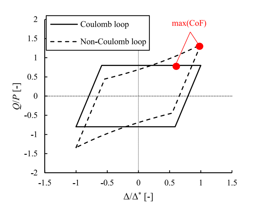
Figure 2. Overestimation using the maxCOF method [2].
Mean value of the tangential force (meanCoF)
In this case, then mean absolute value of each cycle is computed. This method is useful in applications in which the sliding part is significantly higher than the sticking part. That is when the velocity approces zero at the beginning and the end of the stroke. Due to the constant sampling rate, the most part of the data points acquired belong to the part of the cycle where the velocity is lower. This can lead to an overestimation of the CoF.
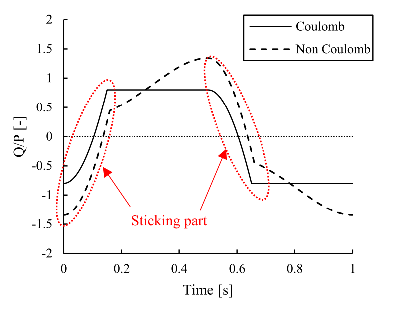
Figure 3. Friction coefficient over time [2].
To focus on the sliding portion of the cycle, only a percentage of the cycle is often considered. Two approaches were found:
- A percentage of the position on a cycle (e.g., from 10% to 90 % of the stroke)
- A percentage around the maximum tangential force (e.g., a window between Qmax and 0.8*Qmax [3]).
There is no consensus on which window should be considered and hence this leads to extra degrees of freedom which need to be considered in advance.
Energy coefficient of friction (ECoF)
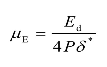
This method consists in estimating the energy dissipation Ed over a tangential force hysteresis loop. The δ* is the slip amplitude. The ECoF (µe) method was proven to be robust, and it evolved to an ASTM standard [4].
Geometric independent coefficient of friction (GiCoF)
A fourth method is presented by Mulvihill et al. considering the shape of the wear scar. The model proved that a hook-like behaviour can results when a parabolic wear scar is considered. Further details can be found in [2] and [5].
References
- Dobromirski J, Smith IO. A stress analysis of a shaft with a press-fitted hub subjected to cyclic axial loading. Int J Mech Sci 1986;28:41–52. doi:10.1016/0020-7403(86)90006-8
- Llavori, I.; Zabala, A.; Aginagalde, A.; Tato, W.; Ayerdi, J.J.; Gómez, X. (2019). Critical analysis of coefficient of friction derivation methods for fretting under gross slip regime. Tribology International, (), 105988–. doi:10.1016/j.triboint.2019.105988
- Wang D, Song D, Wang X, Zhang D, Zhang C, Wang D, et al. Tribo-fatigue behaviors of steel wires under coupled tension-torsion in different environmental media. Wear 2019;420–421:38–53. http://dx.doi.org/10.1016/j.wear.2018.12.038.
- G02 Committee. Guide for Determining Friction Energy Dissipation in Reciprocating Tribosystems. ASTM International; n.d. doi:10.1520/G0203-10R16.
- Mulvihill DM, Kartal ME, Olver AV, Nowell D, Hills DA. Investigation of non-Coulomb friction behaviour in reciprocating sliding. Wear 2011;271:802–16. doi:10.1016/j.wear.2011.03.014.
Leave a Reply
You must be logged in to post a comment.


Assuming a correct statistical analysis in table 1 means, that most reviewers didn´t know the different types of coefficients of friction, otherwise they would have request these in their reviews (see Tribotest 2006; 12: 133-147).
I think, that the representations of evolution of hysteresis by Fouvry&Kapsa et al. as shown in “Tribology International 39 (2006) 1005–1015” is much more visual then the introducing diagram of the present paper.
Some basics can be found in Plint&Plint “Tribology International, August 1985, Vol. 18, No.4, p. 247-249
Basics on dissipated energy can be found in: Fouvry&Kapsa, Wear of Materials, 1985 ; WEAR 252 (2002) 375–383 ; Tribology International 39 (2006) 1005–1015 ;
This paper not shows much new.
Fretting tests go back to Sikorsky fretting test rig in 1950s or even before in WWII for pitch control of propellers.
I loved seeing our article analyzed on tribonet :). In response to Dr. Woydt, the main contribution of this article lies in demonstrating that researchers do not accurately report the techniques used in their experimental trials. Our analysis shows a clear influence of the calculation method on the friction coefficient value, and most of those who report it use the worst of the methods. This speaks volumes about the state of how research work is reported in tribology.