M. Michalec is a PhD student and junior researcher at Brno University of Technology in Czechia. During his studies he gained insignt into tribology and machine design. He is currently working on projects related to large-scale hydrostatic bearing design and development.
Hydrostatic bearings
06.10.2021
Hydrostatic bearings are a particular type of bearings that work on the principle of separating sliding surfaces using pressurized fluid: air, oil or any other type of lubricant. This is in contrast with hydrodynamic bearings, where the separation of the sliding surfaces occurs naturally due to relative motion of the surfaces and their geometry. One of the most important drawbacks of hydrodynamic bearings is that in order for the oil film to form, the surfaces must be moving, but also have a “curved” geometry. The principles of hydrodynamic lubrication are discussed in another article.
For the hydrostatic bearings, the separating lubricant film is introduced into a contact by an external pressure, thus a good lubrication can be provided independently of the speed or geometry. Hydrostatic bearings can be divided into two main parts – the pad (often referred as the hydrostatic bearing itself), and the hydraulic circle. The bearing pad contains a recess groove (or several grooves in case of multi-recess pad types), ensuring there is sufficient area to lift the bearing load. The pressurized fluid flows into the recess through the inlet hole (see Figure 1). The hydraulic circuit must be able to withstand the pressures generated during the lifting phase. The fluid pressure profile in the recess area is constant and it gradually decreases, at the outlets, to the outside pressure (usually atmospheric pressure).
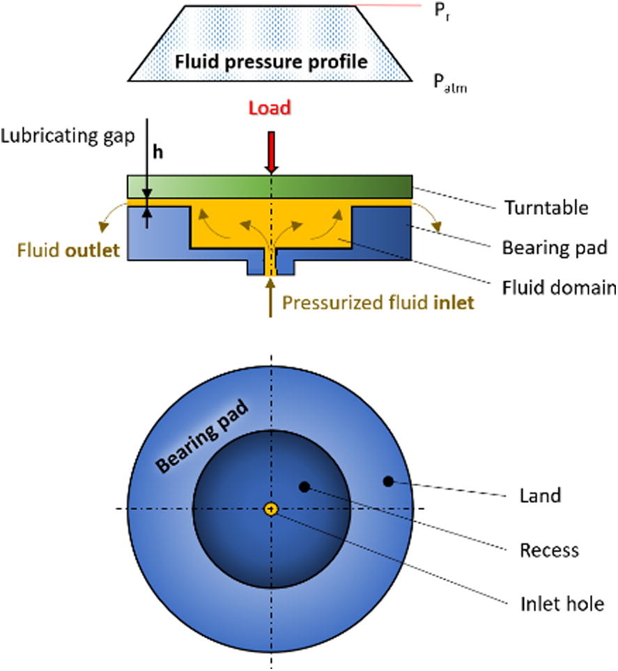
Figure 1 Scheme of the open-type hydrostatic bearing pad and fluid pressure distribution (reprinted from [2] under licence CC BY 3.0).
Hydrostatic lubrication is beneficial due to the lack of contact between the sliding surfaces, which are fully separated by a thick lubricating film (usually 1-100 µm). Therefore, little or no wear is present, and the coefficient of friction is generally very low (depending on the speed, lubricant properties, and bearing geometry). High stiffness and vibration damping result thanks to the fluid film,. Moreover, no stick-slip effect occurs during normal working conditions, thus a very precise motion can be achieved.

A continuous pressurized fluid (e.g. oil) feed is required during operation to achieve proper function. This leads to higher energy requirements, but also significantly higher initial costs related to hydraulic system.
Hydraulic circuit consists of an oil tank, filter, pump, and safety elements. Measuring devices, such as flowmeters and pressure sensors, provide information about the inlet flow to the bearing and fluid pressure in the hydraulic aggregate, respectively. If necessary, a cooler is added to stabilize the lubricant temperature. In case of an unexpected shut down or a hydraulic fluid supply failure, a safety element is usually included (especially for large bearings). Usually a hydraulic accumulator is used which is able to supply the required system pressure until bearing stops. For multi-pad or multi-recess bearings, restrictors are used to compensate eccentric or asymmetrical loading, pad misalignment, or dynamic loading. Thus, a constant film thickness is guaranteed.
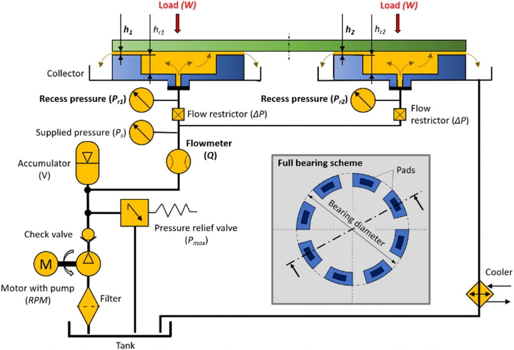
Figure 2 Full scheme of the hydraulic circuit and cross section of two hydrostatic pads of a large multi-pad hydrostatic bearing (reprinted from [2] under licence CC BY 3.0).
Hydrostatic bearings are used in a wide range of applications – from small spindles and guideways (millimetres) to large-scale turntables, machining centres, space telescopes, and antennas, etc.. The methodology of hydrostatic bearing design is well described in the book by Bassani and Piccigallo [1]. The design of such bearings of large-scale was further extended in an article by Michalec et al. [2].
The calculation is based on the fluid mechanics principles. For simple bearing pads (e.g., circular, square, rectangular), analytical equations can be used for a rapid calculation and design. The hydrostatic bearing design begins with pad size determination to withstand acting loads. The minimum recess area can be obtained using eqn.:

(1) 
where W is the applied load, and pr is the recess pressure. Subsequently, the required flow can be determined. For a circular recess following equation can be used.
(2) 
where h is film thickness, µ is dynamic viscosity, and r1 and r2 are recess and pad radius, respectively. Other important parameters can be supplied pressure, friction and pressure losses, or stiffness and damping.
Some non-basic geometries (e.g. four-recess pads – Figure 3) can be calculated using coefficients, as described in the book Applied Tribology: Bearing Design and Lubrication by Khonsari and Booser [3]. The non-derived shapes can be obtained using experimental modelling or electric field analogy plotting [4]. For more complex shapes, numerical simulations are appropriate and widely used.
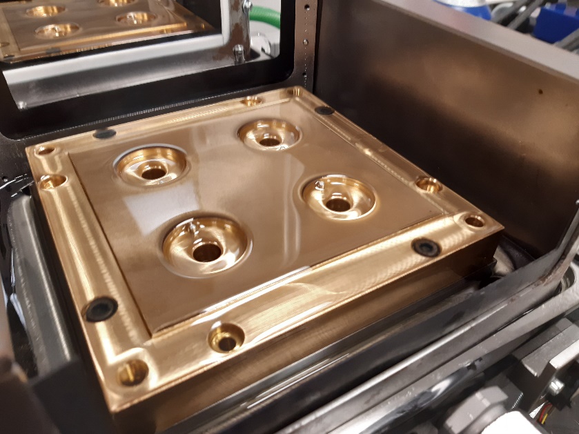
Figure 3 Example of four-recess hydrostatic linear pad (own gallery).
The review publication by Liu et al. [5] indicates that research on hydrostatic bearings is growing, this might be a result of the latest developments in hydraulics control and manufacturing precision. The latest research is aimed at numerical simulations of the lubricant flow in the pad, possibly combined with FSI (Fluid-Structure interaction) methods to gain insight into the deformation of the solid bodies during operation. This is related with manufacturing and precise assembling of bearing solid bodies, which influences the bearing performance. When it comes to large dimensions hydrostatic bearings, i.e. bearings over 10 meters in diameter, manufacturing, transportation, and assembly further increases the complexity of the component. In the near future, major developments on hydraulic circuit optimization and feedback control according to online diagnostics of the lubricating film layer are expected.
References
- [1] R. BASSANI and B. PICCIGALLO. Hydrostatic Lubrication. 22, Elsevier B.V., 1992. ISBN 10: 044488498X.
- [2] M. MICAHLEC, P. SVOBODA, I. KŘUPKA and M. HARTL. A review of the design and optimization of large-scale hydrostatic bearing systems, Engineering Science and Technology, an International Journal. Volume 24, Issue 4, 2021. Pages 936-958. ISSN 2215-0986, DOI: 10.1016/j.jestch.2021.01.010.
- [3] M. M. KHONSARI and R. E. BOOSER. Applied Tribology: Bearing Design and Lubrication. Chichester, UK: John Wiley & Sons, Ltd, 2017. ISBN 9781118700280. DOI: 10.1002/9781118700280
- [4] A. M. LOEB. The Determination of the Characteristics of Hydrostatic Bearings through the use of the Electric Analog Field Plotter, A S L E Transactions, 217-224, 1958. DOI: 10.1080/05698195808972333
- [5] Z.F. LIU, Y. M. WANG, L. G. CAI, Y. S. ZHAO, Q. CHENG and X. M. DONG. A review of hydrostatic bearing system: Researches and applications. Advances in Mechanical Engineering. 2017, 9 (10). ISSN 1687-8132. DOI: 10.1177%2F1687814017730536
Leave a Reply
You must be logged in to post a comment.
Well explained
Cleared my doubt!!
Thanksss
Contact me at [email protected]
Mr. Scheid about design