
Administration of the project
Surface Fatigue
22.08.2019
Table of Contents
What is surface fatigue?
Surface fatigue is the failure on the top layer of a body due to repeated loading. It can be differentiated from other types as it only occurs on the surface. It appears mainly in the form of microcracks and can propagate to other parts of the body, if left unchecked. Surface fatigue can have various causes, including:
- Repeated impact
- Repeated shear stresses
- Fretting wear, or wear that is caused by a oscillating contact between two members
Surface fatigue is a common problem with gears. When gears with rough edges and insufficient lubrication come together repeatedly, they produce a cyclical stress. This cyclical stress can create discontinuities on the surfaces of the gear. As repeated stress is continuously applied to the gear, the discontinuities may turn into microcracks or micro pits on the surface of the gear. This can ultimately lead to a complete failure of the gear [1].
Surface fatigue in impact contact
Impact is a high force or shock that occurs in a short period of time. When surface fatigue is active the cracks form like in the case of sliding contact, but now the hard white layer is the main cause. Material removal by delamination or spalling.

Figure 2: Demonstration of surface fatigue due to impact

Delamination: It is the process of crack propagation through weak interface of below white layer.
Spalling: It is the process of crack propagation parallel to the flow lines in deformation zone.
Surface fatigue in a sliding contact
In addition to surface pitting, repeated sliding contact may also cause horizontal subsurface cracks to grow. The surface is deformed plastically, but a compressive stresses restrains crack growth in the surface layer. Subsurface, where the compressive stress is lower, cracks start to initiate around discontinuities, such as hard inclusions and voids, or around dislocation pile-ups.
The cracks grow horizontally under deformed layer, coalesce and finally lead to detachment of thin sheets. This kind of wear is also called as delamination wear.

Figure 3: Deformation of surface layer and delamination of the deformed layer

The key to surface fatigue is in the contact type and the stresses it creates. Maximum shear stresses at contacts lies beneath the surface and especially peak values can be high in small area contacts. Still cracks can be initiated from the surface also (surface flaws, particles etc.). Contact shear stresses enables the crack growth [2].
Surface fatigue in lubricated contacts
Under elastohydrodynamic lubrication, surface fatigue often results from denting on a surface due to hard or soft particles. The dents in the surface create what are known as berms. Over time and with repeated high loading, pits develop where the surface breaks apart. With continued high loading, the pits become larger.
Surface fatigue is influenced by the particular lubricant being used, including its base oil, additives, viscosity selection and particle contamination. Synthetic oils can provide better protection at higher temperatures than mineral oils with the same viscosity grade and additive package. This is due to the fact that synthetics can have a higher viscosity index. In other words, the viscosity of synthetics may change less with an increase in temperature.
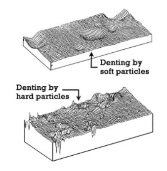
Figure 4: Denting on a surface
Anywhere rolling contact occurs in machinery there is potential for surface fatigue. This would include rolling-element bearings (along the base of the raceway). Gears also have rolling contact, which usually occurs around the pitchline. Cams and rollers are other examples of where you can see rolling contact and thus possible surface fatigue [3].
Surface fatigue in gears
Gear design is commonly bounded by the requirement that the gear should carry high loads at high speeds with minimal size and weight. Therefore, a correct pre-diction of possible gear failure already in the gear de-sign phase is crucial to ensuring the optimum gear design [4]. Gears fail due to several mechanisms, most often due to surface pitting of gear teeth fanks. Surface pitting is in fact the principal mode of failure of mechanical elements that are subjected to rolling contacts,like gears, bearings, shafts, etc., and governs the surface life of a component under applied load [5]. Gear pitting is shown in figure 5.

Figure 5: Gear pitting
Pitting is expected to occur first on the pinion due to the higher number of revolutions and hence higher number of teeth contacts relative to the gear. This region is subjected to the highest loads due to single tooth pair contact, dynamic effects and the fact that the sliding and rolling velocities act in opposite directions [6].
Micropitting generally occurs under elastohydrodynamic lubrication (EHL). When the oil film thickness under EHL becomes too thin at the gear pitch line, surface asperities will begin to come into contact. When these asperities contact each other on opposing surfaces and under high load, they cause elastic or plastic deformation, which leads to micropitting. Extreme pressure (EP) additives are often necessary, in certain cases they can be very chemically aggressive to surfaces and cause micropitting. These types of additives also become more active with higher temperatures. Some researchers claim oils that do not have EP additives will exhibit a maximum resistance to micropitting. An oil’s ability to protect against micropitting can be determined using the FZG FVA 54 test [3].
The complete fatigue process of micro-pit formation consists of the following stages :
- crack initiation;.
- crack growth;.
- breaking away of the surface material layer.
The total service life of a mechanical element under the fatigue loading can roughly be divided into the period required for crack initiation and the period required for its propagation until the final surface failure. Consequently, the number of stress cycles (N) required for the occurrence of pitting can be deter-mined from the number of stress cycles (Ni) required for the appearance of the initial crack in the material and the number of stress cycles (Nf) required for a crack to propagate from the initial to the critical crack length,when the uncontrolled crack growth is expected and pit formation is imminent [7]:
N=Ni+Nf
Real-life case: Hatfield rail crash, 2000
At 12.23 on Tuesday 17 October 2000, train ID38 travelling from London Kings Cross to Leeds derailed roughly 0.5 miles (0.8km) south of Hatfield Station. This incident is widely known as Hatfield rail crash. It was carrying one hundred and seventy passengers and twelve GNER staff. Four passengers were killed and over seventy people were injured, four seriously, including two of the GNER staff. The investigation said that trains passing on rails over a long period of time had caused rolling contact fatigue. Spalling of the running surface to around five millimetres (0.2 in) deep and 100 millimetres (3.9 in) long occurred [8].
Controlling surface fatigue
Selecting the right viscosity is key in reducing surface fatigue. Higher loads will require higher viscosity, while lower loads allow for lower viscosities. Speed can also have an effect on surface fatigue. At lower speeds, the film thickness will decrease. Likewise, at higher speeds, the film thickness can increase. This is another factor to consider in selecting the correct viscosity for your application. The operating temperature also plays a role in surface fatigue. As the temperature increases at the contact area, the oil’s viscosity becomes lower and film thickness decreases. As the temperature increases, a lubricant with too low of a viscosity will become thinner and not provide adequate protection, leading to an increased rate of surface fatigue. If an extreme pressure (EP) oil is used, the EP additives become more reactive at higher temperatures and can offer protection from adhesive wear. Of course, too high of a viscosity can also generate excessive heat. This heat that is caused by too high of a viscosity will lead to accelerated oxidation. If oil analysis is not used to determine the remaining useful life and trigger the need for an oil change, the oil will break down and not provide sufficient protection [3].
About the Author
The article is written by .
References
- [1] https://www.corrosionpedia.com/definition/6359/surface-fatigue
- [2] https://www.slideshare.net/SonamPaljor/surface-fatigue
- [3] https://www.machinerylubrication.com/Read/29276/micropitting-surface-fatigue
- [4] Blake JW, Cheng HS. A surface pitting life model forspur gears. ASME Journal of Tribology 1991;113:712 8
- [5] Johnson KL. The strength of surfaces in rolling contact.Journal of Mechanical Engineering Science1989;203:151 63.
- [6] Suresh S, Ritchie RO. Propagation of short fatiguecracks. International Metals Reviews 1984;29:445 76.
- [7] S. Glodez , Z. Ren, J. Flasker, Surface fatigue of gear teeth flanks, Computers and Structures 73 (1999) 475-483
- [8] Train Derailment at Hatfield: A Final Report by Independent investigation Board (2006)
Be the first to comment