Administration of the project
Friction Brakes
05.10.2021
Table of Contents
What is a friction brake?
A brake refers to a device that primarily plays the role of slowing down or bringing to a halt an object in motion such as a vehicle, a bike, train, an airplane, or roller-coaster. One of the most discussed braking systems are the ones used in vehicles.
A friction brake performs its function by pressing a brake pad against the moving part. As a result of it, a friction force opposing the direction of the moving part develops. In the process, heat is generated from the kinetic energy of the moving object.
The phenomena of friction in braking systems have been extensively covered since the beginning of the 20th century. The popularity of the topic emanates from the notion that brakes represent one of the major safety components in automobiles and their failure could lead to catastrophic consequences.
During the entire braking action, it is essential that the friction force is high and stable. This should apply to any condition including a wide range of contact temperatures, contact pressures and relative velocities between the static and moving parts of the break, including any environmental changes.
Manufacturers mostly focus on the design and improvement of the materials used in the brakes (both the static and dynamic components). In the recent years, more efficient braking systems that are cost-effective, lighter, and smaller with a high capacity for the conversion of kinetic energy to heat have reached the automobile market. Additionally, other parameters are nowadays considered: environmental friendliness, high stability with minimal need for maintenance, and improved reliability.

What are the 3 types of brakes?
The history associated with the development of friction brakes dates to a few centuries ago. Nonetheless, the most prominent advances took place after the beginning of the industrial revolution. During this time, the purely mechanical brake systems were enhanced while the electromagnetically, pneumatic, or hydraulic activated systems permitted a more efficient way of controlling pressure that would help to bind the friction surfaces.
Two major designs can be used to describe friction brakes in terms of the principal operation mode; train “block” brakes and car “disc” and “drum”.
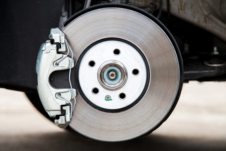
Fig. 1 shows a schematic of a disk brake. When the pedal is stepped on, pressure is generated on the disc brake pads through a fluid that activates the piston leading to “squeezing” of the rotating disc. Braking then occurs due to the friction between the disc and the pads.

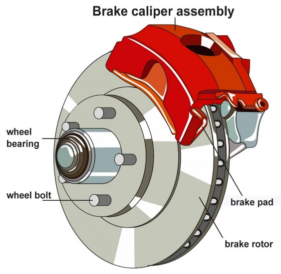
Automotive Friction Brakes, Fig. 1 disk friction brake.
Fig. 2 shows an example of various brake pads. High-performance discs exhibit a surface with attributes of semi-radial continuous grooves (as in Fig. 1). Most discs have a flat machined surface.
Drum brakes are the second type of friction brake and it uses two brake linings of semi-circular shape mounted in a “drum” which is the interior of the cylinder. When pressure is applied on the brake pedal the piston pushes the brake linings to the exterior making them press against the interior of the rotating drum. The resultant friction causes the moving object to brake. Fig. 3 represents a typical drum brake system.
Block brake is the third friction brake with frequent usage (Fig. 4). This braking system uses a brake shoe resembling the one used in horse-drawn carriages. In this system, the braking occurs when a non-moving block presses a wheel in motion. It is commonly used in trains.
Most applications use its specific friction brake design thereby making it hard to portray all the braking systems. Nonetheless, it is important to note that the three examples of friction brakes discussed before are widely used and many alternative designs are modifications of disk, drum, and block braking systems. For instance, the typical configuration of aircraft brake depicted in Fig. 5 is a modification of a disc brake with four rotors (discs). In such a case the stationary discs (stators) have been replaced by “squeezing pads” to allow the rubbing against the rotors’ surface when the hydraulic pistons are pressurized. On a similar note, block brake modifications are also applied in elevators and trams.
Up to this point, the discussion has centred on “dry brakes” where brake fluid is not used to lubricate the countersurfaces. Consequently, where durability is essential, then heavy-duty brakes that are “liquid-cooled” or “wet” are used in a similar way as shown for dry brakes. However, in wet braking systems, the operation is conducted in a closed oil-lubricated systems that use “wet friction.” With that in mind, the dry brakes show a kinetic friction coefficient between 0.2 and 0.7 while that of wet brakes is approximately 0.1. Each type of friction brake has its advantages and drawbacks and designers benefit from using the most appropriate brakes for each application. For example, the disk braking system have a more efficient cooling than the drum brakes while drum brakes are more protected from the environment than the disk brake configuration.
The process of friction leads to wear and induces vibration that contributes to noise. The lifespan of a braking system is mainly determined by the wearing of the brake pads, making the topic relevant from an environmental perception. Additionally, the worn particles released due to wear can negatively affect living organisms. On the other hand, the brake noise poses an impact on the warranty costs of an automobile.

Automotive Friction Brakes, Fig. 2 brake pads.
Friction Brakes Design and Safety
The brake systems structure has become highly standardized over time. Nevertheless, particular things need to be done to most designs such as modeling, extensive testing, and performance calculations before final approval as per legal standards and corresponding regulations. The regulations and standards differ among various countries, but the safety and reliability of the brakes are of concern everywhere.
The physical properties of the components determine the design of the brakes as they are in great part responsible of the friction generation, the heat dissipation, and ultimately the effective stopping due to friction. Their wear resistance determines the lifespan of the brakes. All the parameters are thoroughly tested in the laboratory and on the field. It is worth noting that friction and wear are system properties which are difficult to measure and conclusions derived from the tests should be assessed by qualified tribologists.
The design of friction brakes should be optimum in various aspects: (1) efficiency in friction and performance, which mainly relies on the coefficient of friction and the normal pressure applied when bringing two surfaces together, (2) durability, (3) available space for installation, and (4) the costs.
As already discussed, friction-induced vibrations and associated noise are critical factors to consider when designing brakes. Currently, considerable enhancement of noise generation has been achieved by modifying the surface roughness and chemistry at the contact.
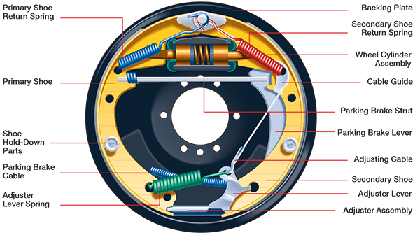

Drum Friction Brakes, Fig. 3 Schematic of a drum brake system.
Material Responsible for Friction
The materials used in brakes are known as friction materials or brake materials. The design of one pair of brake materials is made to last throughout the entire lifespan of an automobile. Since the brake shoe, brake pad, or brake lining wears faster than the counter surface, these can be easily replaced with minimal costs. On the other hand, the disc or drum (countersurface) are rarely replaced as they are design to last longer.
In a contemporary friction brake, the materials of choice, besides generating enough friction, they must fulfil other roles such as damping of vibrations, providing a feeling of good brake, protection against corrosion through cleaning the countersurface, sensing wear, etc. As a result, the brake material comprises numerous components known as composite materials.
Overall, brake linings/pads exist in three broad categories that include organic materials, sintered metallics, and ceramic matrix composites.


Block Friction Brakes, Fig. 4 Block brake.
Organic Materials
Characteristically, organic materials comprise 10-30 ingredients bound together by a polymer matrix. The individual ingredients can influence multiple attributes, which makes their role to be categorized in terms of friction modifiers, binders, reinforcing agents, and fillers. For example, friction modifiers influence the level of friction based on the present materials.
The reinforcing components play a primary role in strengthening the entire composite. They include metallic fibres and their distinct particles (Al, Cu, steel, Fe, and CuZn), ceramic and mineral fibres, and their constituents (ZrSiO4, ceramic wool, wollastonite, and carbon fibre), and pulp or polymer fibres (such as acrylic fibre and Kevlar). Friction modifiers, on the other hand, are significant in influencing friction levels. Mostly they are either solid lubricant (e.g., metal sulphides and graphite) and abrasives (namely Al2O3, SiC, and Kaolite). Fillers generally present stable thermal attributes and cheap ingredients that occupy some volume with little effect on performance. Barium sulphate (BaSO4) is one of the most popularly used fillers. Binders are resins that bring all the particles together, for example, phenolic resin, polyimide, and cashew nut shell liquid resin. Different rubbers namely nitrile butadiene rubber and styrene-butadiene rubber are used to combine resins to enhance the damping characteristics of the system. On the other hand, the highest thermal stability has been observed in phenolics compared to other modifier options.
Numerous components and their allotropic modifications have been utilized in the formulation of brake linings with “organic” properties. However, it might be hard to address all of them as this is beyond the scope of this article. Besides the major material classifications already discussed, some modifications are still being utilized especially in wet friction applications. They include wood, paper, and cork.
Three major categories of friction materials emerge namely semi-metallic linings, organic linings of non-asbestos materials, and low metallic linings (also known as low steel). Semi-metallic materials constitute enormous amounts of steel chip/iron powder. However, metals are absent in non-asbestos organic materials although alternatives contain Cu additions with low metallic brake linings representing a “hybrid” of lower metals than semi-metallics.
The average friction coefficient has varying levels of between 0.3 and 0.7 for organic friction affiliated with countersurfaces in dry systems and about 0.1 in wet brakes systems. A high friction level makes the brake linings noisier, hence, the addition of lubricants influences the mixing and moulding process. However, organic friction materials have a major limitation of thermal effect, which reduces friction levels with heightening temperature. As a result, they are generally effective up to around 300o C.
Sintered Metallics
Sintered metallics’ matrix typically comprises sintered bronze coupled with other metals namely tin, iron, and nickel. Additionally, there are other components solid lubricants such as graphite or MoS2, and ceramic abrasives like ZRSiO4. Iron and nickel increase the composite’s strength while tin and graphite act as lubricants at high and low temperatures respectively. When sintered metals are compared to organic materials, it is noted that the former can withstand temperatures as high as 1000o C and that is why they are used in airplanes. The dry brakes and wet brakes in these materials have a coefficient of friction of 0.2-0.5 and 0.1, respectively.
Ceramic Friction Materials
These materials are majorly utilized in high-end applications like high-speed trains, aircraft brakes, and racing cars where the heat dissipated through kinetic energy is high enough to burn organic materials or melt metallic materials. The popularly utilized systems are the C/Cs (carbon/carbon composites) that comprise a carbonaceous matrix enhanced using carbon fibre. The rotors and stators displayed in Fig. 5 are of aircraft and they are made of C/C composite. The alternatives of these composites in the form of C/Cs are exhibited in terms of charred resin matrix that is reinforced by chopped pitch fibres and dry CVI (carbon vapor infiltration) reinforced by ex-PAN (polyacrylonitrile) carbon fibre. These composites can be substituted by other ceramics, e.g. silicon carbide.
Ceramic materials are quite advantageous in terms of possessing high thermal conductivity, low coefficient of thermal expansion, low particular mass, and highly strong in both low and high temperatures. As a result, they can be used in high temperatures of about 1500o C. Nonetheless, ceramic materials are sensitive to humidity, which affects their rate of wear and the stability of their coefficient of friction. Additionally, they are susceptible to oxidation when the temperature exceeds 400oC. This issue can be rectified through the application of antioxidant protection on the exterior edges of the brake materials as shown in Fig. 5 or developing a carbon fibre alternative with high ceramic content in matrices such as SiC or boron nitride.
Up to this point, the discourses in the paper have covered brake linings and pads. The countersurfaces of numerous brakes comprise metallic components like iron and steel. High-end automobiles and aircraft have their discs/rotors fitted with ceramic composites whose microstructure practically resembles the pads and will not be discussed further.

Fig. 5 aircraft brake showing the four rotors that can be “squeezed” between five stators for braking.
Relationship Between Brake Wear and Environment
The wear of brakes is quite a significant parameter in their utilization as it is related to their lifespan. Most systems have efficient cooling and proper dissipation of heat. Just like the coefficient of friction, the wearing depends on numerous factors namely temperature, pressure sliding speed, and the chemistry between the friction couple structure and the environment. Currently, there is no linear affiliation that can describe wear in relation to distance or the time of brakes application. Every material exhibits unique performance based on usage. For example, an airplane brake can remain efficient for lifetime landings when maintained appropriately or last for a short period when maintained poorly. The outcomes can be similar for automobiles too. This implies that there is a need to avoid factors that maximize brake wearing such as temperature, speed, pressure, and adverse environmental conditions.
There other factors associated with wear include black dusts (Fe3O4) and red dust (Fe2O3). They are a major concern because of the noise they produce in automotive brakes. Additionally, they these debris are periodically released, they are airborne and nanometric in size. The issue has been addressed for asbestos. However, it remains unclear what the current braking system produces and the impact of the debris on life and the environment in general. It is anticipated that there will be more regulations to address the impact of friction brakes from an environmental perspective.
Testing of Brakes
The brakes system has a complex pattern, in fact, it is difficult to predict the use of a braking system. As a result, it is hard to predict all the scenarios involving braking. Nonetheless, the friction attributes of brakes and the materials involved in the manufacturing are thoroughly tested. The testing begins in the laboratory followed by subscale and full-scale tests, bench testing, and real field testing to evaluate performance in a wide range of environmental conditions. Organizations such as governmental agencies, SAE, and trade organizations review the rigorous standards for braking systems. The testing aims to answer various questions about the brakes such as sensitivity to temperature variation, pressure application, speed of engagement, and ability to survive different environmental conditions. These tests are carried out under standardized conditions likely to be applied across the globe.
Top bench testing
Testing the materials used in brakes can be performed using full scale dyno test. However, this is costly and alternatively the materials can be tested on sample level. In this case, the screening is fast, cheap and requires limited material samples. On a sample level the break materials are tested using tribometers. Some manufacturers produce special units and accessories to match the need for brake testing application. Universal Tribometer from Bruker (UMT-Tribolab) is one of them, see the figure below. You can read further information on brake material testing using UMT-Tribolab here.

Conclusion
Friction brakes constitute a paramount component of safety in all applications with braking systems. Reports have associated many accidents with brakes failure. Challenges emanating from debris, noise, vibrations, and wear lead to a reduced braking efficiency and lifespan. Further development is required to address these issues involving advanced materials and novel designs.
Further Reading
A.E. Anderson, Friction and wear of automotive brakes, friction, lubrication, and wear technology. ASM Int. 18, 568–577 (2004), https://doi.org/10.31399/asm.hb.v18.a0006374
B. Bhushan, Introduction to Tribology (Wiley, New York, 2002)
P.J. Blau, Friction Science and Technology (Marcel Dekker, New York, 2008)
B. Breuer, K.H. Bill (eds.), Brake Technology Handbook (SAE, Warrendale, 2008)
P. Filip, L. Kovarˇı´k, M.A. Wright, Automotive brake lining characterization, in Proceedings of 15th Annual SAE Brake Colloquium 1997, P-319 (SAE, Warendale, 1997), p. 41–61
R. Limpert, Brake Design and Safety (SAE, Warrendale, 1999)
R.A. Michael, Key element of wet brake and clutch design, in International Off-Highway and Powerplant Congress and Exposition, September 1992. SAE Technical Paper # 921660 (SAE, Warendale, 1992)
R.J. Shinavski, K.C. Wang, P. Filip, T. Policandriotes, Carbon fiber-reinforced boron carbide friction materials, in Development in Advanced Ceramic and Composites, ed. by M. Brito, P. Filip, C. Lewinsohn, A. Sayir, M. Opeka, W.M. Mullins (The American Ceramic Society, Westerville, 2005), pp. 187–194. ISBN 1-57498-261-3
E.M. Tatarzycki, T. Webb, Friction and wear of aircraft brakes, friction, lubrication, and wear technology. ASM Int. 18, 582–587 (2004)
Lyu, Y., Ma, J., Åström, A.H. et al. Recycling of worn out brake pads ‒ impact on tribology and environment. Sci Rep 10, 8369 (2020). https://doi.org/10.1038/s41598-020-65265-w
Bruker https://www.bruker.com/
Be the first to comment