







Fretting Wear: Key Causes and Proven Prevention Methods 2026
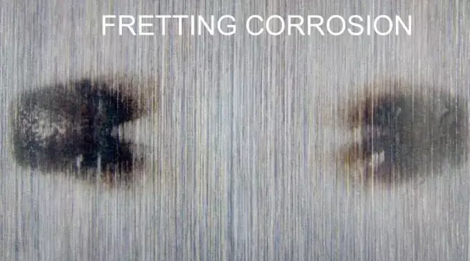
TL;DR: Fretting wear is surface damage caused by very small oscillatory motion between contacting parts that appear to be static. Fretting corrosion occurs when that micro-motion repeatedly removes protective films, exposes fresh material, and lets oxides or corrosion products form abrasive debris inside the contact. It matters because tiny vibration amplitudes can reduce fatigue life, increase electrical resistance, loosen joints, and damage implants, bearings, splines, and bolted assemblies.
- Key takeaway: Fretting is driven by small-amplitude cyclic slip, not ordinary continuous sliding.
- Key takeaway: Damage usually combines adhesive wear, abrasive wear, oxidation, and sometimes fatigue wear.
- Key takeaway: The most important control variables are displacement amplitude, normal load, tangential force, contact geometry, material pair, surface condition, environment, and cycle count.
- Key takeaway: Prevention usually means reducing relative motion, increasing contact stability, separating surfaces with lubrication or coatings, and lowering local stress concentration.
- Key takeaway: Always report the slip regime and test conditions; fretting resistance is not a single intrinsic material property.
- Common use cases: bolted joints, electrical contacts, bearings, gears, aerospace joints, orthopedic implants, wire ropes, and transport vibration damage.
What is fretting wear?
Fretting wear is a localized type of wear caused by repeated small-amplitude oscillatory motion between surfaces that are nominally at rest. Typical motion amplitudes range from tens of micrometers in bolted joints, splines, and electrical contacts down to nanometers in microelectromechanical systems (MEMS). In many fretting contacts there is no visible macroscopic sliding. Instead, the center of the contact may remain stuck while the edge experiences microslip. In a ball-on-flat contact, for example, the central region can be in stick because normal pressure is high, while the periphery slips when tangential traction overcomes static friction. This mixed stick-slip condition is one reason fretting damage often appears at contact edges.
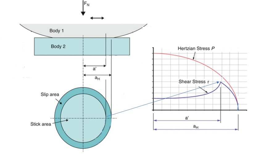
Figure 1. Stresses in a fretting contact
What to notice: the highest risk regions are often near the contact boundary, where partial slip, stress concentration, oxide rupture, and crack initiation can coincide.
What is fretting corrosion?
Fretting corrosion is fretting wear accelerated or modified by chemical reaction with the environment. The oscillatory motion breaks protective surface films, exposes fresh metal, and produces wear particles. In air or humid environments, these particles and exposed surfaces can oxidize. In steel contacts, hard iron oxides may become trapped in the interface and act as a third-body abrasive. Fretting corrosion often appears as pits, grooves, reddish-brown or black oxide debris, polished contact patches, or dark rings around contact zones. The same component can show adhesion, abrasion, oxidation, and fatigue cracking at the same time, so diagnosis should be based on contact conditions and surface evidence rather than color alone.
Why does fretting matter in engineering?
Fretting is dangerous because the initiating motion can be extremely small. A joint can look clamped, static, and well designed while still experiencing microslip under vibration, cyclic loading, thermal expansion, or transport. The practical consequences include:
- Reduced fatigue strength: fretting fatigue strength can be much lower than plain fatigue strength because cracks initiate at highly stressed contact edges.
- Loss of fit or preload: debris formation and surface damage can alter contact stiffness, loosen joints, or change alignment.
- Electrical failure: oxide debris in connectors can increase contact resistance or create intermittent signals.
- Accelerated material loss: trapped debris can create a self-sustaining abrasion-and-oxidation cycle.
- Biomedical risk: implants, screws, plates, and modular junctions can experience fretting-assisted degradation under cyclic body loads.
How does fretting wear happen?
Fretting usually develops through a sequence of mechanical and chemical events. The details depend on material, environment, geometry, and slip regime, but the core mechanism is:
- Film breakdown and adhesion: oxide or passive films rupture at asperities, allowing direct contact and local adhesive junctions.
- Debris generation: oscillatory shear breaks junctions and removes small fragments from the surface.
- Debris trapping: because the displacement amplitude is small, particles often remain inside the contact instead of escaping.
- Oxidation or corrosion: exposed material and debris react with the environment; corrosion products can be harder or more abrasive than the base material.
- Third-body abrasion: trapped particles roll, compact, or plough, increasing material removal or changing the coefficient of friction.
- Crack initiation: repeated normal and tangential stresses create high local stress at contact edges, where fretting fatigue cracks may start.
What slip regimes control fretting damage?
The same material pair can behave very differently depending on whether the contact is in partial slip, mixed slip, or gross slip. This is why fretting resistance should not be reported as a single value without test conditions.
| Slip regime | What happens in the contact | Typical damage pattern | Engineering concern |
|---|---|---|---|
| Partial slip | Central stick zone with microslip near contact edges | Edge damage, small debris bands, early crack initiation | High fretting fatigue risk even when visible wear is modest |
| Mixed slip | Stick and slip zones change during the cycle | Combination of oxidation, debris accumulation, and local cracking | Transition regime; small changes in load or amplitude can change failure mode |
| Gross slip | Most or all of the contact slides during each cycle | More uniform wear scars, high debris generation, friction loops with larger area | Higher wear volume; often measured with reciprocating fretting tests |
What parameters affect fretting wear and fretting corrosion?
Fretting is governed by the whole tribological system: contact mechanics, materials, surface topography, environment, and loading history. The most important parameters are listed below.
| Parameter | Why it matters | Practical design note |
|---|---|---|
| Displacement amplitude | Controls whether the contact remains in partial slip or enters gross slip. | Reduce vibration, increase joint stiffness, or redesign geometry to avoid damaging microslip. |
| Normal load or contact pressure | Affects real contact area, adhesion, frictional shear, and the size of stick zones. | Higher preload can suppress slip in some joints but may also raise contact stress. |
| Tangential force | Determines whether local shear exceeds the friction limit. | Lower cyclic shear through alignment, damping, or load-path changes. |
| Contact geometry | Controls pressure distribution and stress concentration. | Avoid sharp edges, small contact radii, and local bending where possible. |
| Surface roughness and texture | Influences asperity contact, film retention, debris trapping, and local stress. | Specify relevant surface roughness parameters, not only a nominal finish. |
| Material pair | Controls adhesion tendency, oxide behavior, hardness mismatch, and corrosion response. | Use compatible pairs; avoid combinations that create hard trapped oxides or strong adhesion. |
| Environment | Humidity, oxygen, temperature, and corrosive species change oxide formation and debris chemistry. | Test in the service environment when oxidation or corrosion is part of the failure mode. |
| Number of cycles | Damage often has incubation, transition, and steady-state periods. | Report cycle count and inspect periodically; early damage may be invisible. |
How is fretting wear tested?
Fretting tests reproduce small-amplitude cyclic motion under controlled contact load, geometry, frequency, environment, and material pairing. They are used to compare materials, lubricants, coatings, surface treatments, and design changes. Commercial fretting testers usually record tangential force, displacement, normal force, coefficient of friction, and sometimes electrical resistance or acoustic emission. The video below shows a typical fretting or small-amplitude reciprocating test operation in a gross sliding regime:
| Test or measurement | Best used for | What to report |
|---|---|---|
| Ball-on-flat or cylinder-on-flat fretting test | Material, coating, lubricant, and slip-regime comparison | Geometry, load, amplitude, frequency, cycles, environment, friction loop, wear volume |
| Fretting fatigue test | Crack initiation and fatigue-life reduction under cyclic bulk stress | Contact pressure, tangential force, fatigue stress ratio, crack location, life to failure |
| Optical profilometry or white-light interferometry | Wear scar depth, wear volume, surface topography | Scan area, filtering, reference plane, volume calculation method |
| Scanning electron microscopy (SEM) and energy-dispersive spectroscopy (EDS) | Debris morphology, oxide chemistry, crack initiation features | Magnification, accelerating voltage, inspected zones, composition method |
| Electrical contact resistance monitoring | Fretting corrosion in connectors and contacts | Current, voltage, contact force, environment, resistance threshold, failure criterion |
Minimum reporting template for fretting tests
- Contact geometry: ball-on-flat, cylinder-on-flat, flat-on-flat, spline, connector, or component-level fixture.
- Materials: grade, heat treatment, hardness, coating, coating thickness, and counterbody material.
- Surface preparation: roughness, cleaning method, texture direction, and any oxide or passive film condition.
- Loading: normal force or pressure, tangential force, displacement amplitude, waveform, frequency, and number of cycles.
- Environment: temperature, humidity, atmosphere, lubricant, corrosive medium, and contamination controls.
- Measured outputs: coefficient of friction, friction loop, wear volume, debris chemistry, crack length, electrical resistance, and uncertainty.
- Slip regime: partial slip, mixed slip, or gross slip, with the method used to classify it.
How do you diagnose fretting corrosion in the field?
Diagnosis should connect the observed surface damage to the loading condition that created it. Fretting corrosion is likely when a nominally fixed joint shows localized oxide debris, polished zones, pits, or edge cracks in a region exposed to vibration or cyclic stress.
| Observed signature | Likely cause | How to verify |
|---|---|---|
| Reddish-brown or black debris around a contact | Oxidized metallic wear debris trapped by small-amplitude motion | SEM/EDS, debris collection, humidity and material review |
| Damage concentrated at contact edge | Partial slip and stress concentration | Contact mechanics estimate, pressure mapping, crack inspection |
| Intermittent electrical resistance | Oxide film or debris in connector interface | Resistance monitoring during vibration, contact force check |
| Polished scar with compacted debris | Gross or mixed slip with third-body layer formation | Profilometry, friction loop shape, wear volume measurement |
| Crack initiating near contact boundary | Fretting fatigue | Dye penetrant, microscopy, fractography, fatigue loading review |
Fretting diagnosis checklist
- Confirm that the contact is nominally static but exposed to vibration, cyclic force, thermal cycling, or transport motion.
- Map the exact location of debris, pits, polished zones, and cracks relative to the contact edge.
- Check whether the damage is one-sided, symmetric, edge-dominated, or distributed across the whole contact.
- Collect debris before cleaning; identify whether it is oxide, coating debris, base-metal particles, or environmental contamination.
- Measure surface profile and wear volume instead of relying only on photographs.
- Review preload, contact pressure, torque history, alignment, stiffness, and vibration source.
- Compare the failed part with an undamaged reference part from the same assembly.
How do you prevent fretting wear and fretting corrosion?
Effective fretting prevention targets the root cause: small repeated relative motion under contact load. The best solution is often a design change that eliminates microslip. When that is not possible, engineers can reduce frictional shear, protect the surface, alter debris chemistry, or move the system into a less damaging regime.
| Prevention method | How it helps | Limitations |
|---|---|---|
| Increase joint stiffness or preload | Reduces relative motion and can keep the interface in stick. | Too much load can raise contact stress or promote cracking. |
| Reduce vibration or cyclic tangential load | Removes the driving force for microslip. | May require system-level redesign, damping, or alignment changes. |
| Use lubrication | Lowers friction, separates asperities, and can carry additives to the contact. | Lubricant may be displaced, oxidized, contaminated, or incompatible with service temperature. |
| Apply coatings or surface treatments | Improves wear resistance, reduces adhesion, or changes oxide/debris behavior. | Coating adhesion, thickness, residual stress, and edge coverage must be validated. |
| Change material pair | Reduces adhesion, galvanic effects, hardness mismatch problems, or harmful oxide formation. | Material changes can affect strength, corrosion, cost, and manufacturability. |
| Modify surface topography | Can improve lubricant retention or reduce damaging asperity contact. | A smoother surface is not always better; test the actual contact and environment. |
| Introduce compliant layers or isolators | Reduces local stress and absorbs vibration energy. | May change stiffness, temperature capability, and dimensional stability. |
Prevention checklist for design reviews
- Can the contact be redesigned so there is no cyclic relative motion?
- Is the preload high enough to prevent microslip but low enough to avoid excessive contact stress?
- Are vibration sources, alignment errors, and thermal expansion paths understood?
- Is the material pair resistant to adhesion, harmful oxide debris, and environmental corrosion?
- Can a lubricant survive the temperature, humidity, load, and life requirement?
- Does the coating or surface treatment remain intact at contact edges and under cyclic shear?
- Has the design been tested in the correct slip regime and service environment?
- Are inspection intervals based on cycles, vibration exposure, or resistance drift rather than calendar time alone?
What is fretting fatigue?
Fretting fatigue is fatigue cracking assisted by fretting at a contact interface. The contact experiences cyclic normal and tangential stresses, and crack initiation often occurs near the edge of the contact where stress gradients are steep. The resulting crack growth behavior can differ from ordinary fatigue because the frictional stress is strongest near the surface and decreases rapidly with depth. In fretting fatigue, a crack can nucleate at stress amplitudes that would not cause failure in a plain fatigue specimen. Once the crack grows beyond the shallow contact-affected zone, its growth may approach ordinary fatigue crack growth behavior. This is why fretting is a major concern in aircraft joints, turbine components, shafts, dovetails, orthopedic implants, and mechanically fastened structures.
Common pitfalls when evaluating fretting
- Assuming no visible motion means no sliding: fretting damage is often caused by motion too small to see.
- Comparing materials without matching slip regime: a material that performs well in gross slip may not perform well in partial slip fretting fatigue.
- Ignoring environment: humidity, oxygen, temperature, and corrosive media can change debris chemistry and wear rate.
- Reporting coefficient of friction without a method: specify whether values come from peak, mean, cycle average, or energy-based analysis of the friction loop.
- Cleaning away the evidence: fretting debris chemistry and location are important diagnostic clues.
- Using surface roughness alone as a predictor: topography matters, but load, amplitude, material pair, and environment must be considered together.
Frequently asked questions about fretting wear
What is fretting wear?
Quick answer: Fretting wear is localized surface damage caused by repeated small-amplitude oscillatory motion between contacting parts that are meant to be stationary. It is common in joints, connectors, bearings, splines, implants, and components exposed to vibration or cyclic loading.

What is the difference between fretting wear and fretting corrosion?
Quick answer: Fretting wear describes the mechanical damage; fretting corrosion includes chemical reaction, oxidation, or corrosion products generated during fretting. In many metals exposed to air, the two occur together because fretting continually exposes fresh reactive surfaces.
What causes fretting corrosion?
Quick answer: Fretting corrosion is caused by microslip that breaks protective films, generates debris, and allows exposed material or debris to oxidize or corrode. The main drivers are displacement amplitude, normal load, tangential force, contact geometry, material pair, environment, and cycle count.

How do I identify fretting damage?
Quick answer: Look for localized pits, grooves, polished scars, oxide debris, dark rings, increased electrical resistance, or cracks at the edge of a nominally fixed contact. Confirm the diagnosis with microscopy, surface profilometry, debris chemistry, and a review of vibration or cyclic loading.
How do I reduce fretting in bolted joints?
Quick answer: Reduce cyclic slip by improving preload control, increasing joint stiffness, reducing vibration, improving alignment, and using appropriate surface treatments or lubricants. Do not simply increase preload without checking contact stress and fatigue risk.

Which coatings work best for fretting wear?
Quick answer: The best coating depends on load, slip regime, temperature, environment, substrate, and whether the main risk is wear, corrosion, or fatigue cracking. Hard wear-resistant coatings, solid-lubricant coatings, nitriding, anodizing, and shot-peened surfaces can help in specific applications, but they must be tested under representative fretting conditions.
Can lubrication prevent fretting corrosion?
Quick answer: Lubrication can reduce fretting by lowering friction, separating asperities, and limiting oxidation, but it is not always permanent or sufficient. The lubricant must remain in the contact during small-amplitude motion and must survive the service temperature, humidity, load, and life requirement.

What is the difference between fretting and ordinary reciprocating sliding?
Quick answer: Fretting uses very small oscillatory displacement in a contact that is nominally static, while ordinary reciprocating sliding usually has larger, deliberate back-and-forth motion. Gross-slip fretting tests may look similar to reciprocating sliding, so the displacement amplitude, contact geometry, and slip-regime classification should be reported.
How is fretting wear measured?
Quick answer: Fretting wear is measured by combining friction-loop data with post-test wear scar measurement, surface profilometry, microscopy, and debris or oxide analysis. For reliable comparison, report geometry, normal load, amplitude, frequency, cycles, environment, material preparation, and wear-volume calculation method.
See also
- Wear
- Fretting wear
- Abrasive wear
- Adhesive wear
- Fatigue wear
- Surface fatigue
- Wear particles
- Wear particle analysis
- Coefficient of friction
- Surface roughness
- Friction
- Tribological surfaces
References
- [1] Fretting Corrosion. R. B. Waterhouse. Pergamon Press, 1972.
- [2] Peter J. Blau, Friction Science and Technology: From Concepts to Applications.
- [3] Zaki Ahmad, Principles of Corrosion Engineering and Corrosion Control, 2006.
- [4] N. Maruyama, Mechanical testing of metallic biomaterials, in Metals for Biomedical Devices, 2010.
- [5] R. B. Waterhouse, Fretting wear, Wear, 1984.
- [6] Gwidon W. Stachowiak and Andrew W. Batchelor, Engineering Tribology, Third Edition, 2005.
Additional testing standards: ASTM G204, Standard Test Method for Damage to Contacting Solid Surfaces under Fretting Conditions; ASTM D4170, Standard Test Method for Fretting Wear Protection by Lubricating Greases.
Last updated: 2026-05-04
Reviewed by: Aydar Akchurin
Canonical URL: https://www.tribonet.org/wiki/fretting-corrosion/
References
- [1] Fretting Corrosion. Von R. B. Waterhouse. 253 S. 306 Abb., 13 Tab. 1972, Pergamon Press, Oxford, New York, Toronto, Sydney, Braunschweig
- [2] Friction Science and Technology: From Concepts to Applications, Peter J. Blau,
- [3] Zaki Ahmad, in Principles of Corrosion Engineering and Corrosion Control, 2006
- [4] Mechanical testing of metallic biomaterials, N. Maruyama, in Metals for Biomedical Devices, 2010
- [5] R.B. Waterhouse, Fretting wear, Wear, 1984
- [6] Engineering Tribology, Gwidon W. Stachowiak, Andrew W. Batchelor, Third Edition, 2005
hello.
i want to enquire whether fretting wear can occur in suspension front forks of motor cycles.
as the front forks continuously undergo reciprocating motion, under contact between hard chrome plating and various sealings generally made up of NBR rubber,PTFE etc, is there any chance of fretting wear on the front forks?
Hello,
I just read the article abot fretting.
Thank’s for that clear explanations.
For me I made the conlusion that bearings installaed at low tmepeatures e.g. -20°C might therefore be more affected by fretting (low temperatures in combination with low absolute humidity).
Is that a valid conclusion?